The specific geometry of a twin screw extruder for powder coating has historically varied for some suppliers, e.g. Werner & Pfleiderer (Coperion), OMC (Picard): whilst remaining consistent for other manufacturers APV (Baker Perkins) and Xtrutech.
Available Extruder Torque:
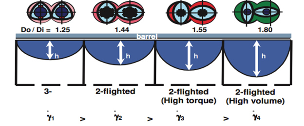
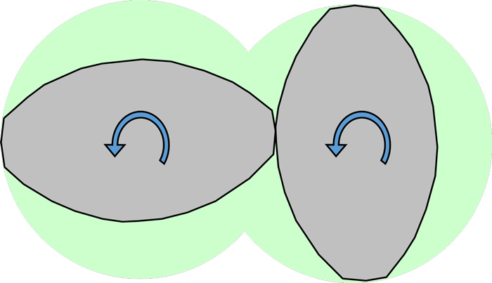
As is clearly visible in the illustration above, the available space within the screw cross section for the torque carrying shaft is greater for the 1.55 geometry variant. For high processing energy resins, such as engineering thermoplastics, this gives significant advantages in terms of the power that can be applied to these materials, with significant productivity advantages for the 1.55 geometry compared with the 1.8 geometry. Most frequently higher energy thermoplastics are limited by the torque capacity of the twin screw. A comparison chart showing different material families is shown below.
Powdercoatings have a processing energy requirement of 0.04 to 0.08 kW/h.kg, compared with well over 3 times this energy input level for the majority of commodity thermoplastics. Using the latest generations of twin screw extruder for powdercoatings, the torque limit of the extruder is not reached. As output is increased, the intake, or feeding limit is reached before any high levels of torque are encountered.
Clearances
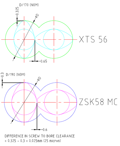
It is often assumed, perhaps based on some historical machinery designs, that the higher free volume Di/Do geometry is designed with significantly larger clearances. The diagram below shows that on the Xtrutech range, this is not the case. Minor differences in clearance are known to exist, but in both cases the clearance is sufficiently small for the processing shear rates within the screw-to-screw and screw-to barrel clearances to play little or no part in the generation of heat within the molten material. Statistically speaking, the passage of a portion of molten resin through the clearances is a rare event, and the highly sheared resin that has passed through the clearances, because of its low apparent viscosity, is also quickly rehomogenised with the melt in the other parts of the screw channel. The close clearances are selected to maintain smooth running of the screws within the barrel, and to allow high screw speeds to be attained without generating any mechanical destabilizing forces within the rotating shaft and screw assemblies.
Channel Depth – Effect on Shear and Elongational Mixing
Evolution of the geometry of a typical twin screw design is shown above, progressing from the early trilobe designs, to the Di/Do variants of 1.55 and 1.8 available today. As the metallurgy and design of the shaft has improved, early design revisions involved increases in both available processing volume, and available processing power. Generally, deeper screw channels are seen by machinery builders, and users as having
Improved intake
Reduced shear input
Lower melt temperatures
Reduced product stress / improved molecular weight retention through processing
Safer venting operation
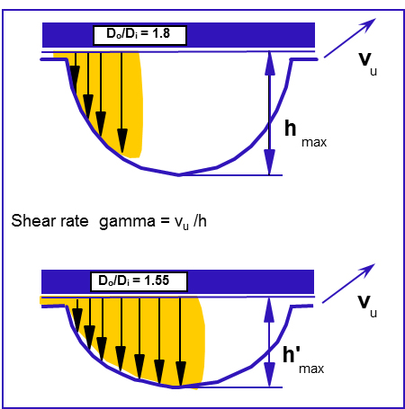
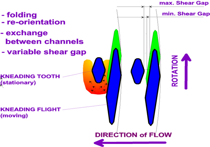
In a partially filled channel, there can arise situations where the shallower channel of the Di/Do 1.55 variant can have a greater material average channel depth, as show in the diagram opposite.
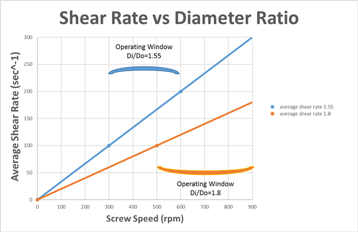
The shallower channel will operate, most frequently, at a higher degree of fill, and this higher fill level means that more material occupies the maximum depth of the channel, resulting in a reduced material average shear rate. In filled channels, this situation is reversed. At a given screw speed, in a filled channel, the average channel shear rate can be calculated, and is found to have a ratio of 5:3, with the Do/Di = 1.8 having the lower shear rate. As a rule of thumb, the shear rate at 300rpm on a Di/Do = 1.55 extruder is the same as that on a Di/Do =1.8 extruder operating at 500rpm.
To illustrate this point, suppose a difficult to disperse material has a threshold minimum shear rate of 100s^-1, which on a Di/Do =1.5 extruder, is achieved at 300rpm. In this case, a well dispersed product is not processed on the Di/Do =1.8 extruder until it is operated at the increased speed of 500rpm. Suppose further though, that the same material also has a thermal shear rate stability limit of 200s^-1. The diagram below shows the operating windows of both extruder geometries under these conditions.
The operating window of the Di/Do=1.55 extends from 300 to 600rpm. Compared with this, the Di/Do extruder has an operating window extending from 500rpm, to a point above the maximum operating speed of 900rpm. In reality, though, these theoretical limits rarely persist for either geometry of extruder, and can normally be overcome by optimizing processing conditions and screw design. However, consideration of only the shear rate and shear flows is kind of missing the point somewhat. Effective mixing uses a balance of shear, and extensional flows. Extensional, or Elongational, flows are the stretching flows that occur when material is squeezed and accelerated. Theoretical work on mixing liquids of differing viscosities found that elongational flows are more effective at droplet break-up, typically by a factor of 2 or more.
Even a basic plastics single screw extruder has plenty of shear flow. Designers have tried lots of different geometries to add elongation flow areas to a single screw, but none have seen significant success. Generally a single screw extruder is good at generating pressure, but is regarded as a poor mixer. Adding a reciprocating action (for example the Buss Cokneader, or the B&P trivolution) does add elongational flow, at the points where the barrel pins move through the gaps in the screw flights.
They perform better in mixing than all other single screw designs, although still some way short in terms of the dispersion quality of most twin screw designs. Some formulations have to be processed twice on a Cokneader to achieve required quality. A twin screw extruder, when the channels become full, has a volume change in the cross sectional channels between the screws that increase and decrease in volume as the screws rotate. These squeezing, or compression expansion forces give rise to a series of alternating extensional flows backwards and forwards along the screws. As the degree of channel fill increases towards 100%, these get more intense, as the diagram below shows. The flows shown on the diagram are measured, rather than theoretical computer based prediction. As the degree of fill increases from ~85% at the top of the diagram, to ~100% at the bottom, the intensity of the flow increases. It is these alternating axial flows that led to the early designs of twin screw extruder being termed “Two Screw Kneaders”.
In terms of geometry, the twin screw that produces the highest amount of elongational flow should provide the best mixing. The amount of material subjected to elongational flow may be calculated as the compression ratio multiplied by the free volume of the screw. A high compression ratio would be an obvious advantage, but the geometry requirements for maintaining a self wiping profile fix most of the cross sectional geometry, and, perhaps surprisingly, the compression ratio changes very little with the Do/Di ratio.
In the same way as in a car engine, where the power output is proportional to the product of engine capacity and compression ratio, the work done by the compression and expansion of material in the kneading blocks is also proportional to the product of volume and compression ratio. Combining these effects shows a significant advantage for the Do/Di = 1.8 geometry, which in this case has more than 30% higher volumes of elongational flow. This analysis does not take into account the operating screw speed. If, as is likely, the Do/Di = 1.8 extruder geometry can be operated effectively at higher screw speeds, this effect will be even greater.
Intake of Low Density Materials
Although considered only in 4th place, intake is an extremely significant obstacle for an extruder designer to contend with. After all, if you can’t get the material into the extruder, you can’t process it at all.
Computer modelling of solid conveying of powder materials is difficult. Standard uniform plastic granules have been successfully (i.e. accurately!) modelled in the feed area of a twin screw only in the past few years, and the analysis of characteristics of powders of different particle sizes, and varying melting points, is beyond computing and modelling capabilities for the present. Solids conveying is very dependent on the frictional characteristics of the feed materials, and these, in turn, are also difficult and costly to measure.
Theoretically, there are 2 competing factors. Firstly, that the deeper channel of the Di/Do = 1.8 design has a higher swept volume, resulting in higher material intake. Secondly, that the low density powder materials have fluid-like characteristics, and that the shallower channel of the Di/Do =1.55 machine design gives less backflow, and greater efficiency of pumping of the solids towards the mixing section of the extruder.
As stated earlier, computational modelling is problematic, and prediction of actual intake performance is done on a try-it-and-see basis. Geometry comparisons are possible, though, using the theories originally developed by Darnell and Mol for single screw extruders in the 1950s. Their simplified model ignored any friction at the screw surface, and showed that solids conveying for similar geometric flight designs can be predicted by a 3 factor product.
Output, Q is proportional to H x D x (D-H)
where H is flight depth, and D is barrel diameter.
Using these 3 factors, the Di/Do = 1.8 can be shown to have a greater theoretical solids
conveying capacity by approximately 18%.
Shaft Cooling
The main objective of screw cooling in any extruder is to enhance the ability of the screw to forward the solid feed into the extruder at the steadiest possible rate. It accomplishes this by providing a more constant and lower coefficient of friction between the screw and the solid premix materials. In essence, the extrusion process is a complex heat transfer system in which the temperature in the various locations inside the barrel controls the friction coefficients between the various solids in those locations at any particular moment. It is this friction coefficient that enables the screw to forward plastic granules and plastic melt, and even more so, to create large amounts of heat through shear energy coming from the extruder drive motor.
Any analysis of the heat balance on the water coolant on a modern twin screw extruder will show that, compared with the extruder drive power, the screw cooling is capable of only a very small proportion of the energy that can be applied to the material by heat, friction and viscous shear. Some observers have, though reported that a significant reduction in melt temperature has been measured as a result of screw cooling. However, it is more likely that the heat reduction is the result of a reduction of the filled length of the extruder, due to the action of the shaft cooling in delaying the onset of melting of the mixture.
With this in mind, in general, the best location for the initial penetration of the screw cooling pipe is at the point where the feed section of the screw ends. The geometry of the screw makes little or no difference to the heat that can be removed through the metal surfaces.
However, the degree of fill has been found to make some difference, and in most cases a lower degree of fill allows low friction to persist for a longer length along the barrel, which is desirable. The Di/Do =1.8 design will operate at a lower degree of fill, as the 18% increase in solids conveying capacity indicated in the previous section will be more than offset by the 40% higher free volume.
Summary
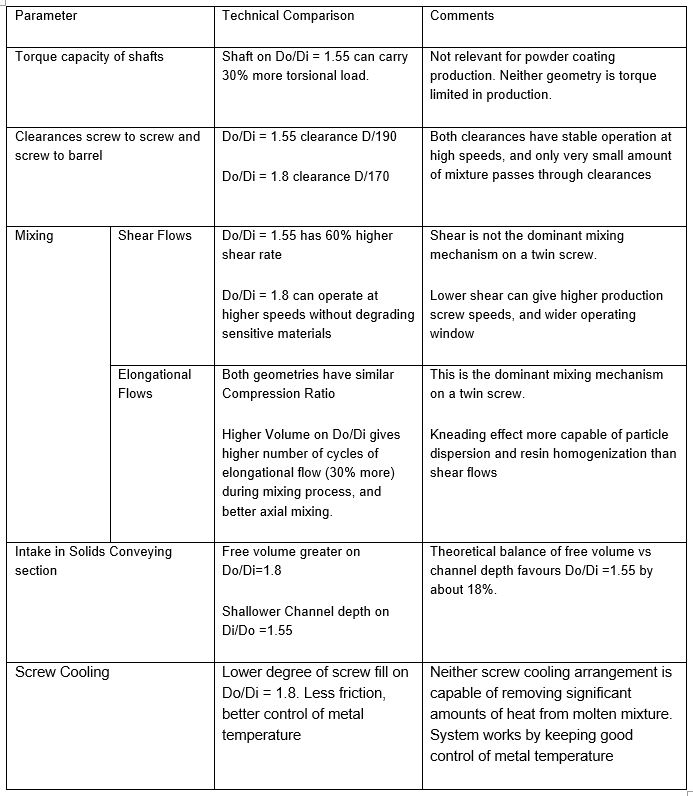
Geometries have been examined in detail across the 5 main process relevant factors.


